Portable retroreflectometers
Dynamic retroreflectometer LTL-M
Thickness gauges
Test kit
Skid Resistance Tester (SRT)
Portable retroreflectometers
Road markings are traffic signs according to § 41 Para. 3 and § 42 Para. 6 StVO (German Road Traffic Regulations) and Section 2 of the ‘Guidelines for Road Marking, Part 1’ (RMS-1). In darkness, markings, particularly on open sections of road, have an important guiding function, as road users have no other means of orientation to call upon.
Road markings are subject to different external influences which lead to a degradation of their traffic-related properties. For decades DELTA has been the world’s leading manufacturer of portable and dynamic systems for the precise and rapid measurement of daytime (Qd) and night-time visibility (RL) and contrast.
We offer various measuring systems for measuring the photometric properties of markings statically and dynamically, all of which can be configured to suit the individual customer.
Test institutions, highway construction authorities and marketing companies require different measuring instruments for testing traffic-related properties, and TDS offers these in the form of a test kit to meet customers’ individual requirements. A mechanical and a digital marking thickness gauge are available for measuring the layer thickness of dry markings (with and without reflective beads).
LTL 3500
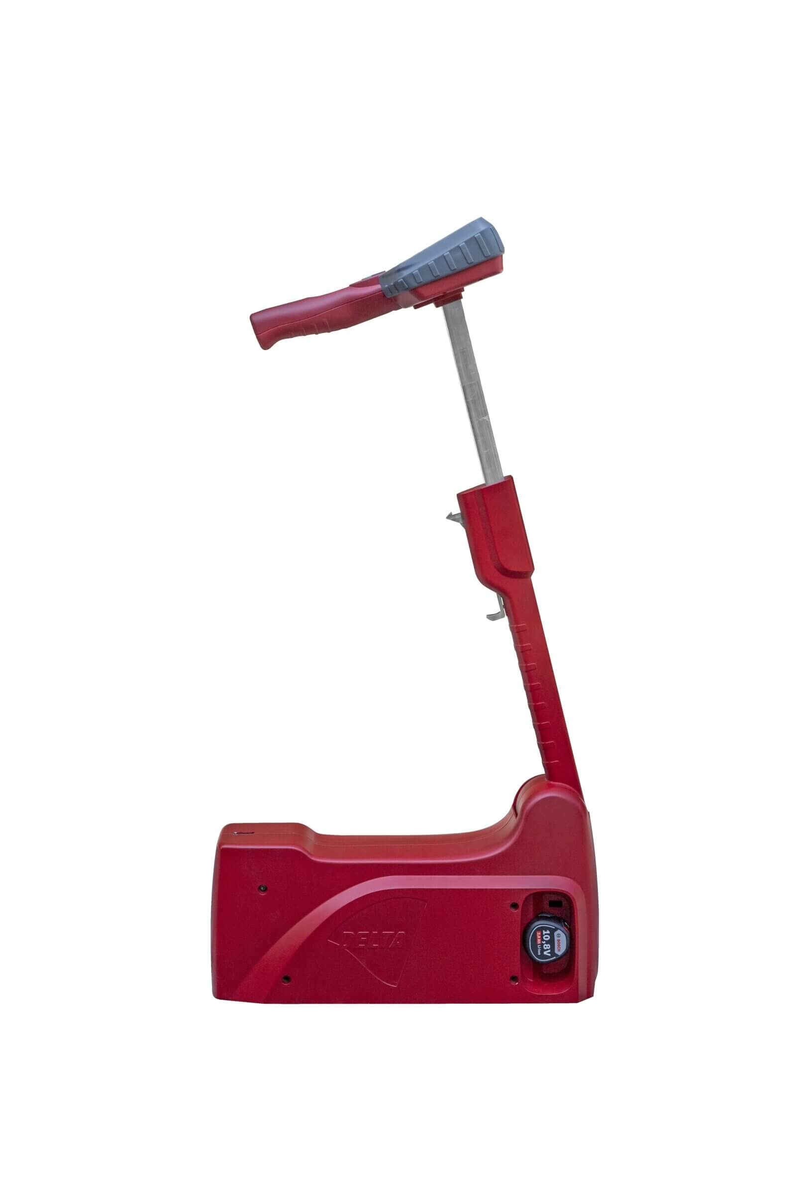
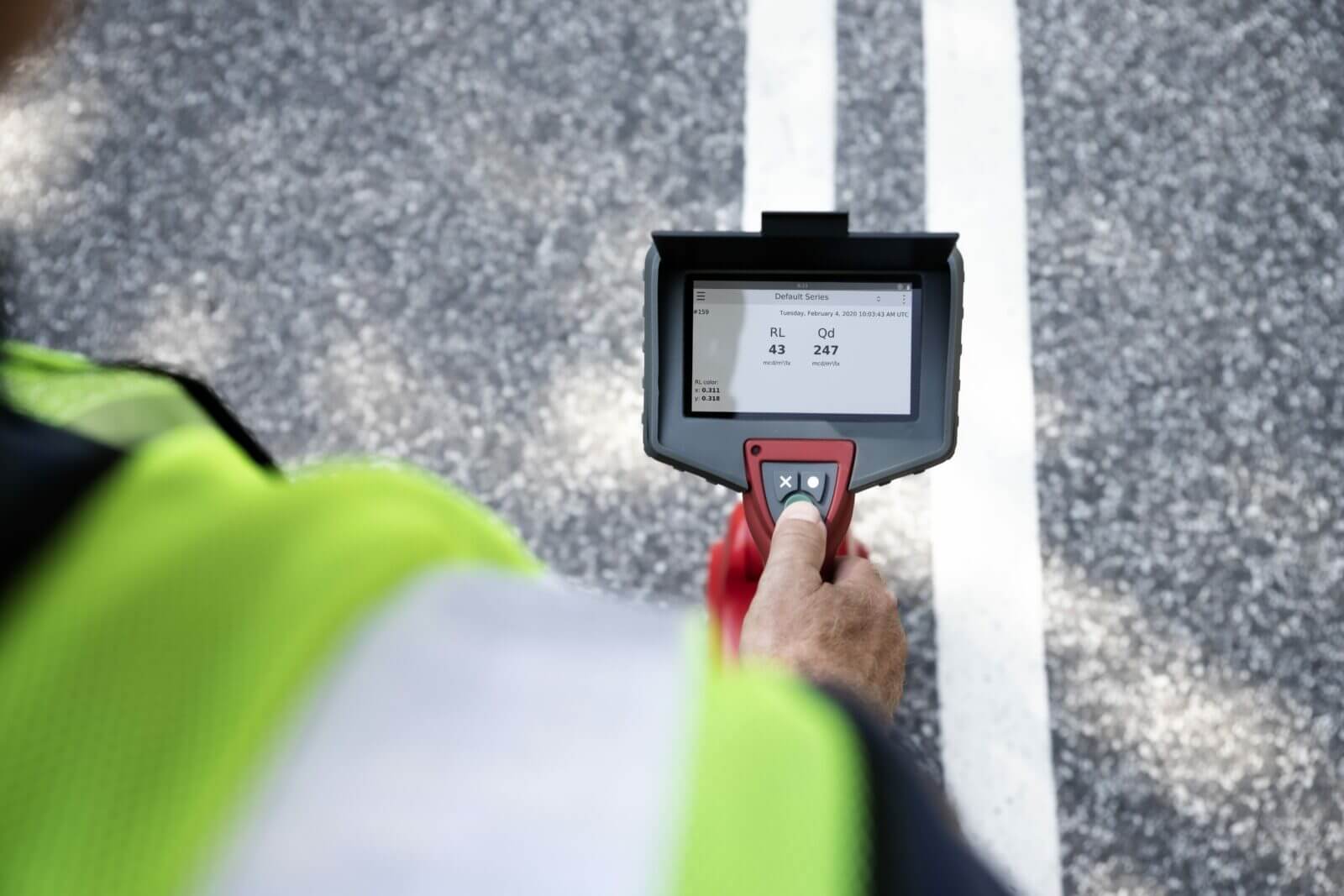
The LTL 3500 introduced at the end of 2020 is the flagship of the lane marking retroreflectometers. It is an extremely compact instrument for measuring the night-time visibility (RL) and, optionally, the daytime visibility (Qd) of road markings. Measurements can be taken both in the daytime and at night on dry and wet markings. The night-time visibility can also be measured in continuous rain.
The LTL 3500 optionally fulfils the requirements of DIN EN 1436 or ASTM E 1710. The scope of supply includes a calibration stand (RL) and, optionally, a calibration reference (Qd) from DELTA’s photometry calibration laboratory, which is accredited by DANAK. The following extras are available as an option:
- Qd function
- Night colour module (x,y coordinates for white and yellow)
- GNSS module (Global Navigation Satellite System)
- Macro and overview camera
- Compass and inclinometer
- External printer
The LTL 3500 is factory-equipped with all the hardware and software modules listed above, which can also be subsequently activated online in a few minutes (e.g. camera, GNSS module, etc.).
LTL 3000
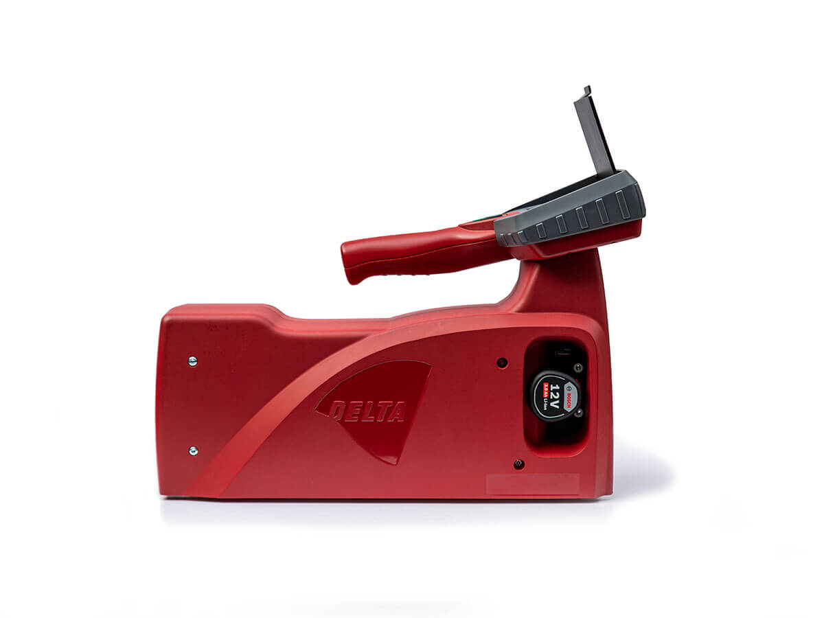
The LTL 3000 retroreflectometer is the latest generation. It is a highly compact instrument for measuring the night-time visibility (RL) and, optionally, the daytime visibility (Qd) of road markings. Measurements can be taken both in the daytime and at night on dry and wet markings.
The LTL 3000 optionally fulfils the requirements of DIN EN 1436 or ASTM E 1710. The scope of supply includes a calibration stand (RL) and a calibration reference (Qd) from DELTA’s photometry calibration laboratory, which is accredited by DANAK. The following extras are available as an option:
- Qd function
- Night colour module (x,y coordinates for white and yellow)
- GNSS module (Global Navigation Satellite System)
| Technical specifications | LTL 3500 | LTL 3000 |
|---|---|---|
| Measuring nighttime visibility dry and wet (RL/RW) underneath the system |  | |
| Measuring nighttime visibility dry and wet (RL/RW) in front of the system | | – |
| Measuring daytime visibility (Qd) | optional | optional |
| Retractbale handle | | – |
| Night colour coordinates (x, y) | optional | optional |
| GPS/GNSS module | optional | optional |
| Macro camera | optional | – |
| Overview camera | optional | – |
| Compass and inclinometer | optional | – |
| Printer (internal) | – | – |
| Printer (external) | optional | – |
| Set of wheels | – | – |
| Colour touch LED display with 3 buttons | | |
| Straylight compensation | | |
| Input user ID and road | | |
| Multi language menue | | |
| One-hand operation | | |
| Suitable for flat and profiled (≤15 mm) markings and agglomerates | | |
| Suitable for white and yellow markings | | |
| Measuring time RL and Qd | < 1 sec. | < 1 sec. |
| Measuring time RL | – | – |
| Documentation of date, time, temperature and humidity | | |
| Dimension measruing field in mm (length/width) | 180/50 | 180/50 |
| Illumination angle RL according to DIN EN 1436 | 1.24° | 1.24° |
| Observation angle according to DIN EN 1436 | 2.29° | 2.29° |
| Light sources | LED | LED |
| Illumination angle Qd | diffuse | diffuse |
| Illumination angular spread (hor./vert.) | 0.33°/0.17° | 0.33°/0.17° |
| Observation angular spread | ±0.17° | ±0.17° |
| Equivalent observations distance | 30 m | 30 m |
| RL range | 0-4000 mcd·m-2·lx-1 | 0-4000 mcd·m-2·lx-1 |
| Qd range | 0-318 mcd·m-2·lx-1 | 0-318 mcd·m-2·lx-1 |
| Typical repeatability | ±2 % | ±2 % |
| Typical reproducibility | ±5 % | ±5 % |
| Temperature range | 0 °C to +60 °C | 0 °C to +60 °C |
| Relative humidity | 20-85 %, noncondensing | < 85 %, noncondensing |
| Capacity measurement memory | > 1 Mio. | > 1 Mio. |
| Interface (USB 2.0) | USB memory stick, WiFi, IOT in preparation | USB memory stick |
| Data xxport | Excel format | Excel format |
| RL calibration standard supplied by accredited laboratory for photometry (DANAK) | | |
| Qd calibration reference supplied by accredited laboratory for photometry (DANAK) | | |
| Charger and battery | | |
| Charging time (battery) | 75 minutes | 45 minutes |
| Dimensions in mm (l/w/h) | 470 x 150 x 280 | 420 x 150 x 300 |
| Weight in kg | 5.6 | 4.7 |
| Carrying case | | |
Using the calibration stand included with the unit, the user can check the measuring accuracy himself at any time. The instrument is supplied in a stable carrying case.
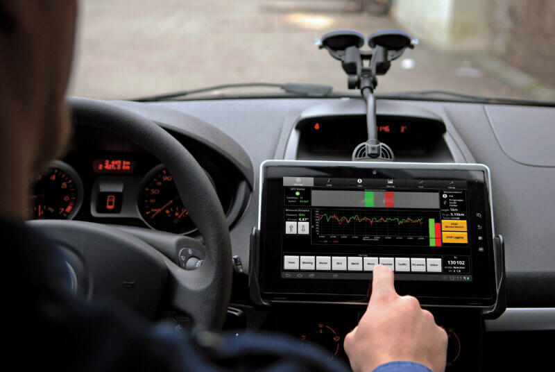
Dynamic retroreflectometer LTL-M
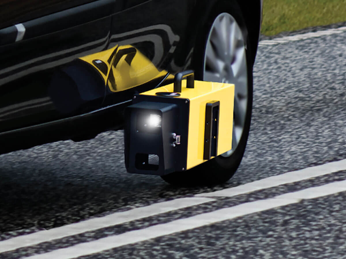
The night-time visibility of markings is measured dynamically with the LTL-M. With the unit mounted on the side of the vehicle, measurements are made continuously in flowing traffic without the need for additional safeguarding or impeding other road users.
The LTL-M has been developed for professional use and is deployed throughout the world. The sensor technology used ensures that external influences (road irregularities, ruts, expansion joints, acceleration, braking etc.) are automatically detected and compensated for during measurement, thus maintaining the required measuring geometry at all times, which ensures high data accuracy.
The system fulfils the requirements of DIN EN 1436 and ASTM-E 1710 and measures the night-time visibility of markings and the contrast in daylight. It also measures the line geometry and missing or defective reflectorised raised pavement markers (RRPMs). The measurements are typically carried out in a speed range of 50 km/h to 120 km/h, whereby the photometric properties of the whole marking are documented and not just parts. The system measuring error is typically ±5% based on the values measured with DELTA portable reflectometers.
The system can be calibrated and the light source changed quickly and straightforwardly on site. The unit is equipped with a precision GPS and can also be supplied with an overview camera and a distance measuring instrument (DMI) as an option. The driver is able to interrupted the measuring process and/or mark measurements as required.
The instrument’s standards are calibrated in DELTA’s photometry calibration laboratory, which is accredited by DANAK, and enables tracking in accordance with the requirements of the PTB (Physikalisch-Technische Bundesanstalt, Germany) and the NIST (National Institute of Standards and Technology, USA).
| Technical specifications | LTL-M |
|---|---|
| Illuminaation angle according to DIN EN 1436 | 1.24° |
| Observation angle according to DIN EN 1436 | 2.29° |
| Illuminaation angle according to ASTM E 1710 | 88.76° |
| Observation angle according to ASTM E 1710 | 1.05° |
| Scale | 1 : 5 |
| Distance sensor/measuring area | 6 m |
| Measuring area | 100 x 100 cm |
| RL measuring range | 0-2000 mcd·m-2·lx-1 |
| Required marking length | > 1 m |
| Width marking | > 50 mm / < 500 mm |
| Repeatability (95 % confidence interval) | 3 % |
| Measurement error per 100 measurements | < 5 % |
| Temperature range (in operation) | 0 °C to +45 °C |
| Measuring daylight contrast | |
| Measuring road studs | |
| GPS module | |
| Automatic compensation for vehicle movements | |
| Colour correction | |
| Calibration standard (DANAK) | |
| LED caution lights front (white) and rear (red) | |
| Tablet PC | |
| Distance measurement instrument (DMI) | optional |
| Overview camera | optional |
Thickness gauges
Mechanical marking thickness gauge
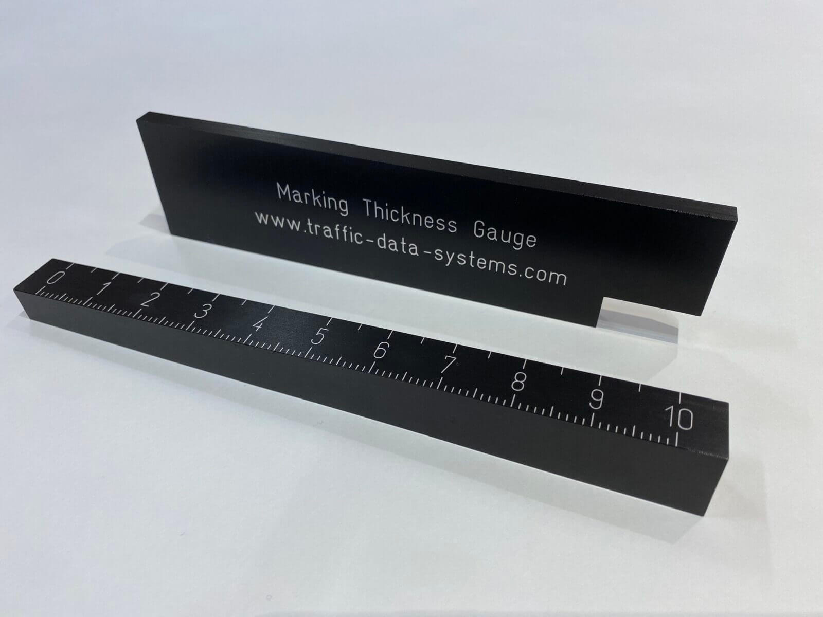
Among other things, marking gangs, highway construction authorities and test institutions check the marking layer thickness (with and without reflective beads) in order to establish that road markings have been applied properly. Our offer includes a mechanical marking thickness gauge (MTG) for carrying out rapid checks on site. Both parts are made from black anodised aluminium and have been developed for use by marking gangs.
| Technical specifications | mechanical MTG |
|---|---|
| Dimensions gauge 1/2, with scale | 222 x 25 x 18 mm |
| Dimensions gauge 2/2, without scale | 200 x 50 x 8 mm |
| Weight | 410 g |
| Material | Aluminium (anodized) |
| Resolution | 0.10 mm |
| Measuring range | 0/+10.0 mm |
| Accuracy | 0.10 mm |
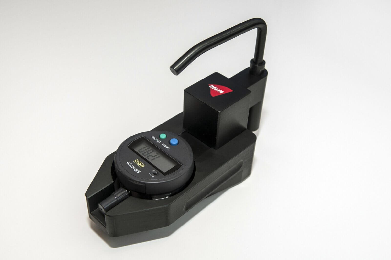
Digital marking thickness gauge
As an alternative to mechanical measurement, we offer a faster and considerably more convenient solution for measuring the marking layer thickness in the form of the digital MTG (Marking Thickness Gauge). The stably built instrument is ergonomically designed and easy to use.
The digital MTG measures layer thicknesses in a range from -12.7 to +12.7 mm. The digital display shows the measurements within fractions of a second. The unit is supplied in a stable plastic case. The instrument comes complete with a calibration certificate.
| Technical specifications | digital MTG |
|---|---|
| Dimensions in mm | 180 x 70 x 130 |
| Weight | 950 g |
| Material | Edelstahl |
| Resolution | 0,02 m |
| Measuring range | -12.7 / +12.7 mm |
| Accuracy | 0.02 mm |
| Display | LED |
| Protection class | IP42 |
| Endurance battery | 20,000 hrs. |
LTL Stripe Scan
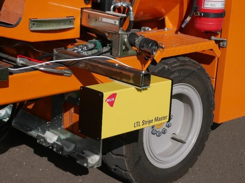
As well as the classical traffic-related properties of lane markings, highway construction authorities are increasingly demanding evidence documenting the correct application of new markings. The objective is to monitor the whole application process to ensure that markings are applied in accordance with the contract and that the materials used comply with the client’s specifications. This is the only way to guarantee that markings give long service.
In order to determine the layer thickness throughout the whole of the application process, DELTA has developed the LTL StripeScan. The LTL StripeScan is mounted on the marking machine and continuously measures the layer thickness of the applied marking using a laser. Detailed information relating to the newly applied marking, including thickness, width and cross-sectional area, can be measured and documented with the help of this system. The data are transmitted via an interface directly to the marking machine control electronics in order to adjust the application process if necessary.
The LTL StripeScan uses a laser that is invisible to the human eye. The device is mounted on the marking machine in such a way that it can scan a 35 cm wide area of the marking and the road (resolution 0.1 mm). The maximum system scanning rate is 180 measurements per second. From the individual data, the system creates a complete 2D profile and calculates a 3D profile of the marking (taking into account the marking machine’s distance measurement counter). The resolution is a function of the speed at which the marking machine is driven. The data are geo-referenced and can therefore be associated with each individual measuring point.
| Technical specifications | LTL Stripe Scan |
|---|---|
| Stripe width ≤ 200 mm | full cross section, accuracy +/- 0.1 mm |
| Stripe width > 200 mm | cross section of edge, accuracy +/- 0.1 mm |
| Output | section average thickness, peak to peak thickness, section area, stripe width |
| Transverse resolution | 0.3 mm |
| Scan rate | 45 Hz |
| Communication | CAN bus |
| Laser safety class | 3B |
| Power supply | 12 VDC (automotive) |
| Dimensions in mm | 135 x 175 x 370 |
| Weight | 3.4 kg |
Test kit
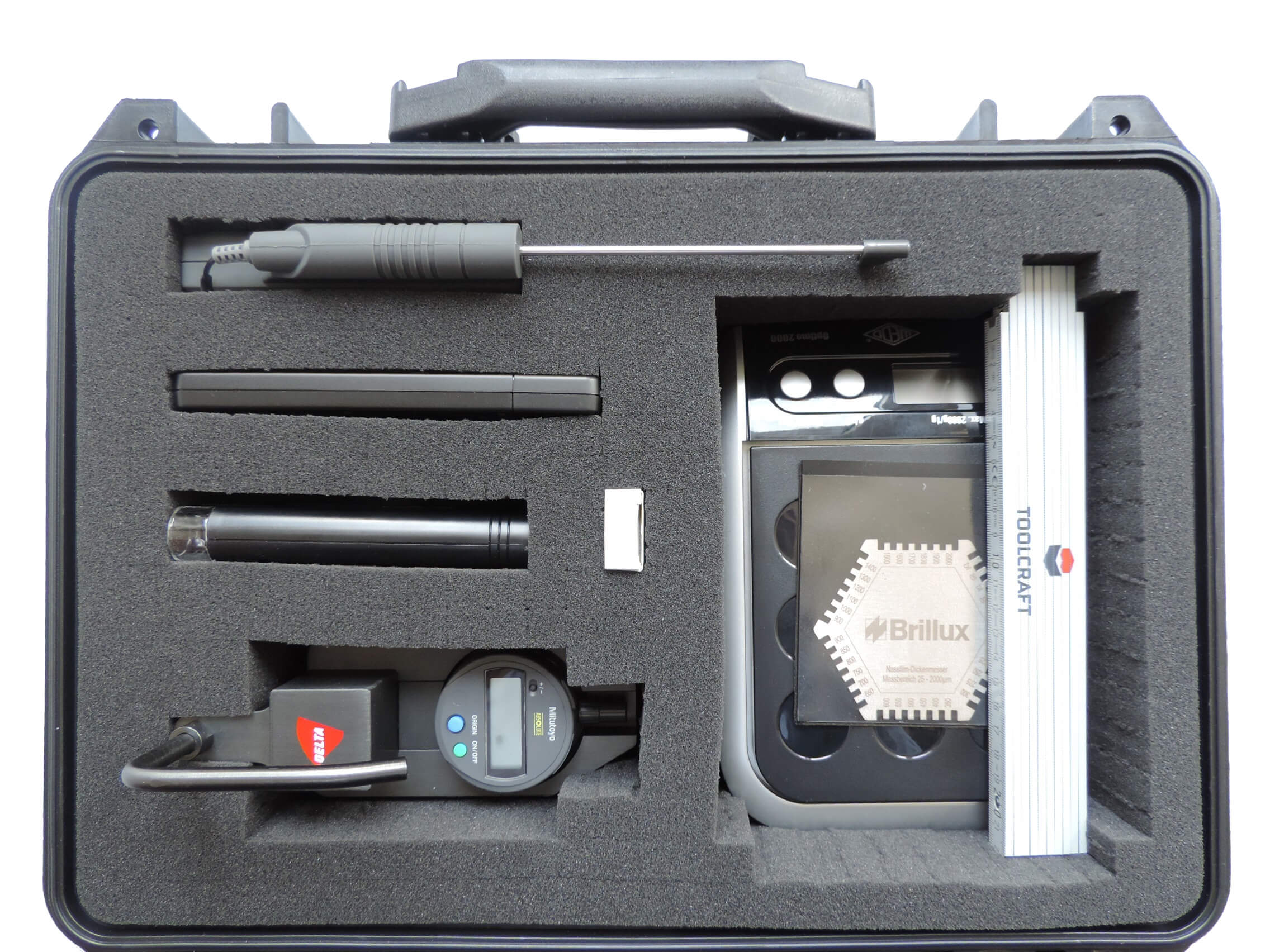
As well as measuring the photometric properties (daytime and at night-time visibility) and the grip of the markings, a series of further measurements during and after the application of the markings is necessary to check that they have been produced correctly. Traffic Data Systems offers the necessary measuring instruments individually or complete in the form of a ‘test kit’.
| Test kit components (individually configurable) |
|---|
| Digital marking thickness gauge (dig. MTG), specifications see above |
| Mechanical marking thickness gauge (mech. MTG), specifications see above) |
| Infrared thermometer (-50/+500°C), on request alternatively thermometer with single probe (-50/+300°C) |
| Hygrometer (measurning error: ±3 %, range: 20 % to 90 %) |
| Rod microscope with integrated illumination (30 times magnification) |
| Measuring comb (measuring range: 25 to 2,000 µm) |
| Linen tester with 8 times magnification and µm indicator scale |
| Scale (measuring scale: 0 to 2 kg, resolution: 1 g) |
| Folding rule (length: 2 m) |
| Propylene outdoor case with pressure compensating valve |

Skid Resistance Tester (SRT)
The Skid Resistance Tester (SRT) is a portable measuring device and is used to determine the skid resistance of traffic surfaces. Skid resistance measurements are also carried out as combined measurements if necessary (measurement method Skid Resistance Tester with Outflow Meter according to Moore). Fields of application for tests include:
- Road surfaces (concrete/asphalt) and road markings
- Pedestrian areas (paved and slabbed surfaces, stairs, crossings, platforms, etc.)
- cycle paths
- Performance review in the course of construction contracts (e.g. road surfaces)
- Pavement condition survey and investigation of accident blackspots
The SRT device is described in the German ‘Technical Test Specifications for Skid Resistance Measurements in Road Construction, Part Measurement Procedure SRT (TP Griff-StB (SRT)’, FGSV edition 2004 as well as ARS No. 19/10:2010-08-27′. The testing of road markings is based on DIN EN 1436 and ZTV M 13.
We offer the Skid Resistance Tester incl. transport case, conversion according to TP Griff-StB (SRT), 44mm circular bubble, additional weights, friction length scale, sliding body according to DIN EN 13036 part 4 edition 2011 and initial calibration.
| Technical specifications | Skid Resistance Tester |
|---|---|
| Skid Resistance Tester | acc. to TP Griff-StB (SRT) |
| Transport case | Case with metal reinforcements and wheels |
| Accessories | Tools and water bottle |
| Total weight | approx. 30kg (incl. case and accessories) |
| Sliding body acc. to DIN EN 13036 (BAM) | included |
| Friction length scale | included |
| Calibration certificate (initial calibration) | included |